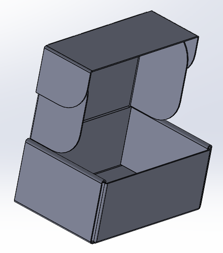
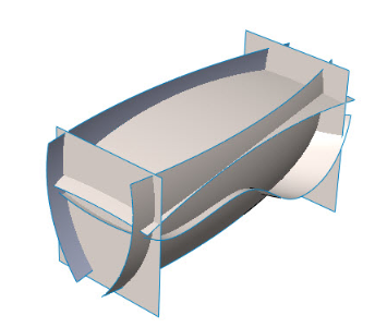
In a simulation study tree right click the top parts folder and select treat all sheet metals as shells or treat all weldments as beams.
Solidworks simulation treat as sheet metal.
You can select the type of a mesh contour plot that becomes visible after meshing in the new dialog box default options plot mesh plot.
You also have the option to first treat sheet metals as solid bodies and then convert manually selected solid faces to shells.
In this tutorial video we will learn how to create a bracket with the help of sheet metal commands like base flange sketched bend and sheet metal gusset.
Welcome to solidworks simulation help.
In this tutorial video i will sketch self cutting sheet metal screw 4x20mm with anti theft fixing head in solidworks with the help of sketch and feature t.
Solidworks offers a suite of simulation packages that enable you to set up virtual real world environments so you can test your product designs before manufa.
You cannot modify the thickness.
The definition of this shell mesh should pull the thickness from the sheet metal definition but i always verify it just in case.
This can be accomplished by creating a new model constructed with sheet metal features base flange edge flange miter flange etc or an existing solid body can be converted into a sheet metal body by using the convert to sheet metal and insert bends features.
When you run a simulation on a part created with the sheet metal tools it automatically converts it over to a shell element body 2d as it s significantly faster to run.
Meshing sheet metal parts in solidworks simulation duration.
The program automatically extracts and assigns the thickness of the sheet metal to the shell.


